
一.Production introduction:
JCZ dual-axis large-format splicing uses JCZ dual-extended axis control board to achieve splicing marking beyond the scope of the field mirror. It is recommended to use a format above 300*300, because the large format is completed by small field mirrors splicing and marking, so there are the advantages of high light intensity, deep marking depth, etc., and simple focusing, but it requires high mechanical precision, so the debugging process is cumbersome.
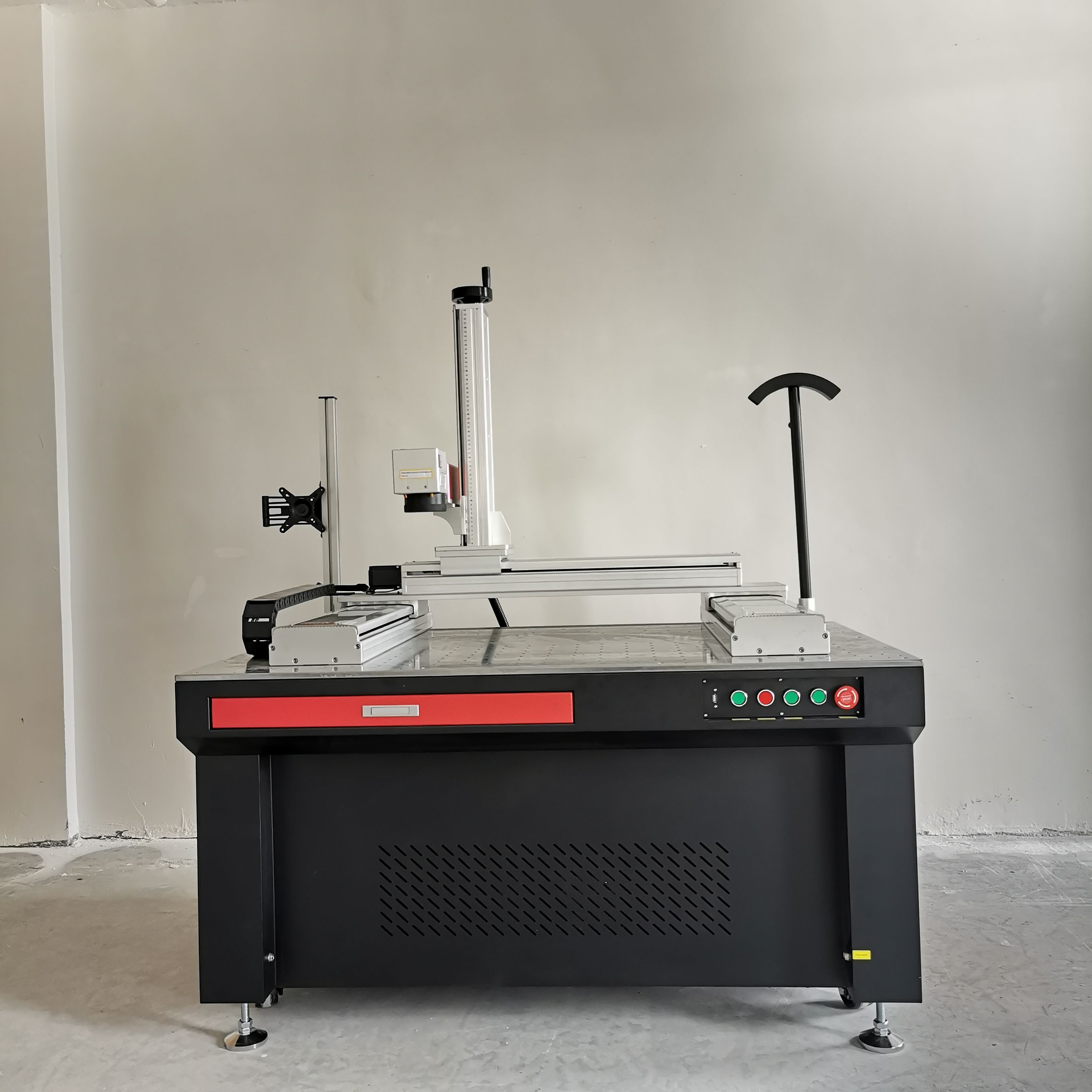
二.Machine installation:
Because some parts will be removed during the delivery process, you need to install them yourself after receiving the machine. What you need to install includes the column and the optical path. For the installation method, refer to the ordinary marking machine.
三. Running test:
After all the hardware is installed, a simple single-run test is required, including light emission and movement tests of each axis.
1.Running test:
After installation, the first step is routine debugging such as light testing and distortion correction.
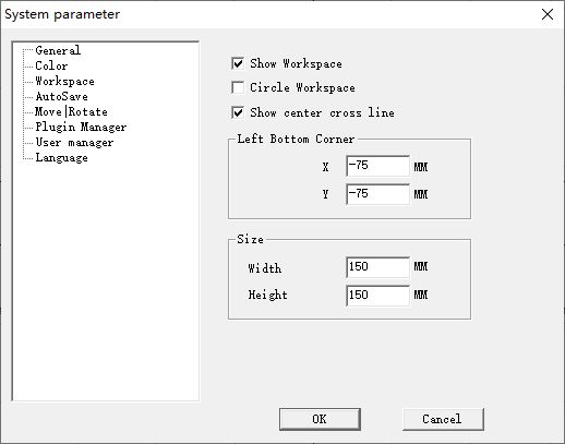
Fill in the position of the center point and the size according to the size of the field lens. Click on the parameters at the bottom of the standard interface, and fill in according to the size of the field lens range.
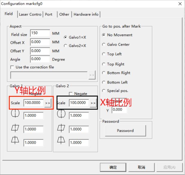
Scale correction, mark the largest box according to the marking range, and then mark it. After measurement, fill in the corresponding scale according to the actual measurement value. For example, the X axis is 150mm, and the actual measurement is 152mm. Fill in the following figure, and the Y axis is the same reason until it agrees.
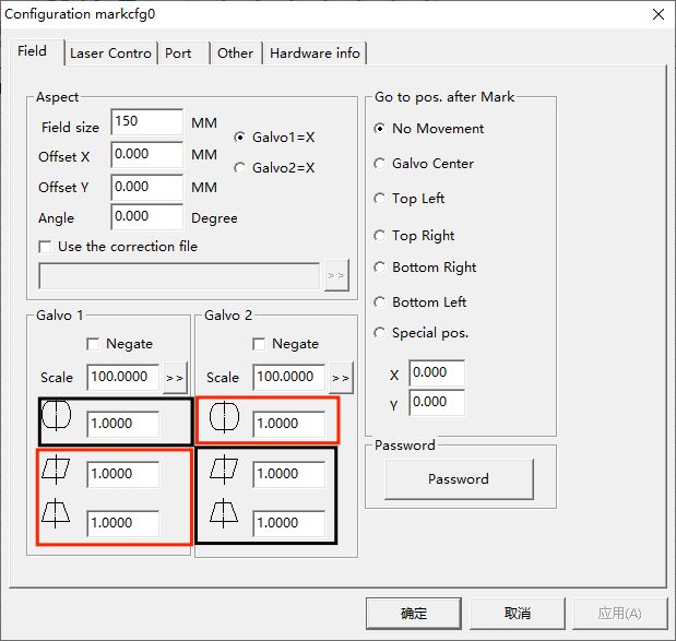
Then fill in the correction parameters according to the measured actual square deformation ratio, as shown in the figure, the Y-axis deformation parameters are in the red box, and the X-axis deformation parameters are in the black box.

The marked frame is a square, without deformation and without imaginary edges.
2.Adjust Two axis:
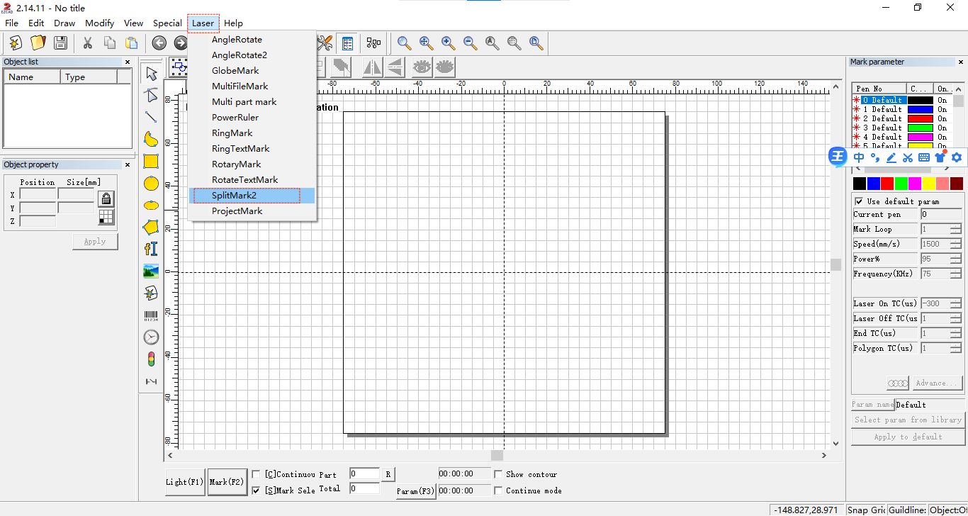
On the top of the software, select Laser -SplitMark2 to enter the SplitMark work page.
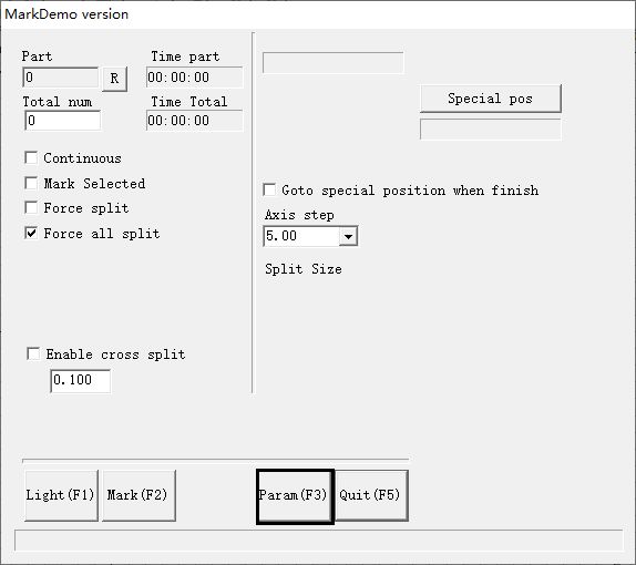
This is SplitMark work page. Now the two external axes have not been opened. Click “F3″ below to enter the external axis setting.
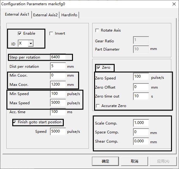
Take the X external setting as an example. After opening, you need to check the enable button, select X as the ID, and fill in Pulses per round below to match the actual motor drive setting, otherwise there will be problems such as lost steps or insufficient movement distance. The minimum Coor is 0, and the maximum distance is filled in according to the actual size of the machine.
Zero setting has three states,This is forward zero return, after the zero point is set, the direction returns to the zero point forward.,This state is the state of reverse zero return. After setting the zero point, the motor reverses to the zero point。,In this state, there is no zero point, and the motor does not return to zero.


After setting the zero return direction of each axis to be correct, it is necessary to calibrate the unique accuracy of each axis. The calibration method is to draw a straight line of 100mm, 200mm, and 300mm, and then perform split mark,measure the marking line after marking, and compare the results. , according to the actual scale, adjust Dist per round until the adjusted
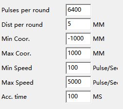
target length is consistent with the marked length.
After the step distance is adjusted, the stitching effect needs to be adjusted. Still draw a horizontal line with a length of 100mm, and place the line in the lower right corner of the entire working range
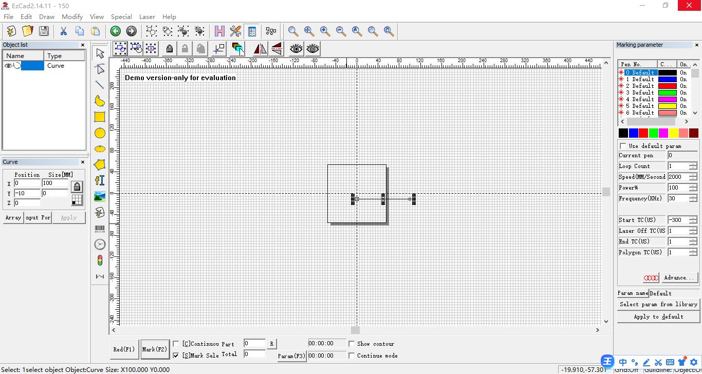
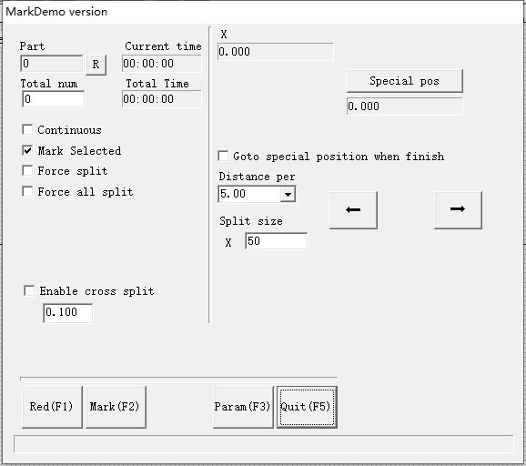
Then click SplitMark,Set the split marking size, set it to 30mm, start marking, and check the effect.
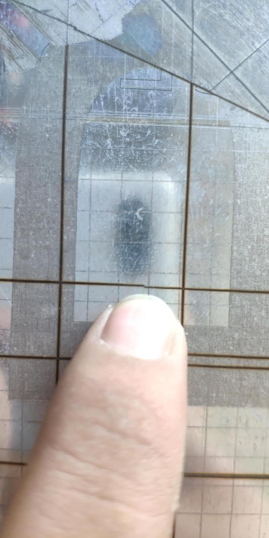
If the splicing effect is as shown in the figure, it means that the field lens is not parallel to the X-axis, and the angle of the galvanometer or the X-axis needs to be adjusted until the interface is flat. The same is true for Y-axis adjustment. If the galvanometer is adjusted to be parallel to the X-axis before, and then this problem occurs during the adjustment of the Y-axis, you need to adjust the perpendicularity between the X-axis and the Y-axis until the adjustment is completed.
3.Marking start:
After adjusting the splicing effect, you can start marking. Marking needs to place the pattern to be marked in the lower right corner of the working range. As shown in the figure, and the range of the graph does not exceed the zero point and the maximum range of the X.Y axis.
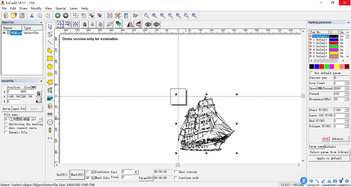
After placing the picture, click SplitMark2, and after setting the split size, you can start marking.
If the stitching problem occurs again during the marking process, please repeat the above operation.
Post time: Feb-23-2023


